Research Topics
Overview (Click to enlarge)
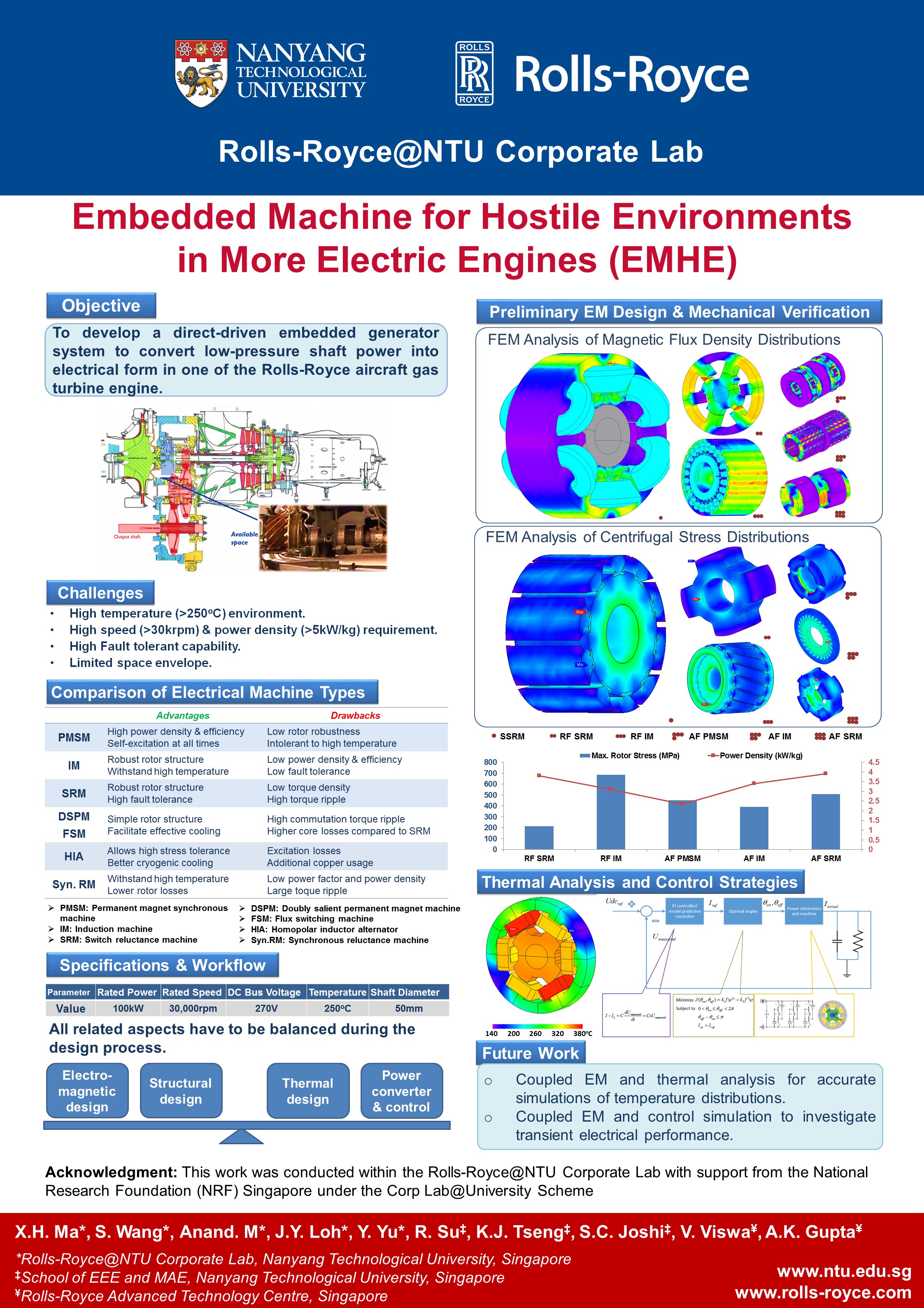
Challenges
Since the machine is directly embedded into the shaft of the low pressure shaft, there are some challenges needed to be considered before doing the baseline design, which include:
Space envelope limitation. The space inside the gas turbine is very limited. Generally there is barely enough for holding a high-power-density electrical machine.
Mechanical limitation on the rotor. The electrical machine requires operations above 30,000 rpm, which restrict the rotor peripheral speed within the safe margin of the rotor materials
High curie temperature affordability for permanent magnet materials in case of demagnetization in the harsh environment (250~300 ℃). Since the location is near the exhausted air outlet, the ambient operating temperature is around 250~300 ℃. Permanent magnet materials (if any), soft magnet iron losses and cooling issues will also affect electromagnetic design.
Larger airgap requirement. It is necessity to stiffen the engine structure to ensure rotor and stator do not come into contact under high acceleration and the whole range of high speed operations.
Comparison of Electrical Machine topologies from Literatutre Review
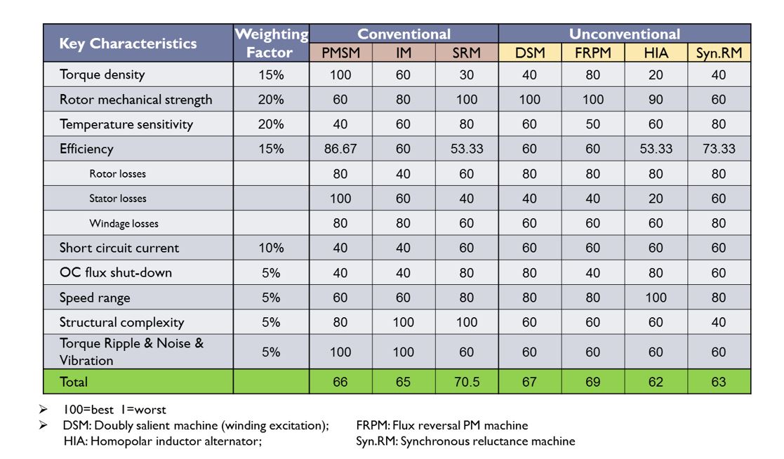
Fig. 1. Comparison of Electrical Machine topologies.
We have also performed preliminary design on five electrical machine topologies, radial flux/axial flux switch reluctance machine, radial flux/axial flux induction machine and axial flux permanent magnet synchronous machine, including theoretical design, electromagnetic FEA simulation, mechanical and thermal verification.

Fig. 2. FEA flux density and rotor Von Mises stress distribution of five machines
They are axial field Permanent magnet synchorpius machine (a), radial field induction machine (b), axial field induction machine (c), radial field switched reluctance machine (d) and axial field switched reluctance machine (e) respectively.
Based on the above literature review and FEM simulation, Doubly salient / Flux reversal machines are proposed which offer the distinct advantages as follows: (1) With SRM prominent features, e.g. simple rotor, absence of PM on rotor, concentrated and isolated phase windings, large self-inductances. (2) Higher power density due to stator independent field excitation. (3) PMs on stator that could be better cooled. (4) Fault tolerant SRM mode in case of PM failure
Design of Flux-switching machine

Fig. 3. 2D view of preliminary designed topologies
The Flux Switching Machine as a doubly salient permanent magnet (PM) brushless machine has seen industrial application in recent years as automotive integrated-starter generators , wind power generators and aerospace generators . This topology has the same high fault tolerance as reluctance machine which has independent concentrated windings. PM or field coil excitation placed on the stator facilitate cooling management. Rotor structure provides strong mechanical robustness succeeding the merits of similar reluctance machine. Therefore it is regarded as an excellent machine topology competitor in applications requiring high speed, high power density, robustness, fault tolerance and cooling convenience. The SegFSM 12/7 is selected from amongst seven topologies due to its acceptable mechanical stress and higher torque capability.
Control algorithm development of Flux-switching machine
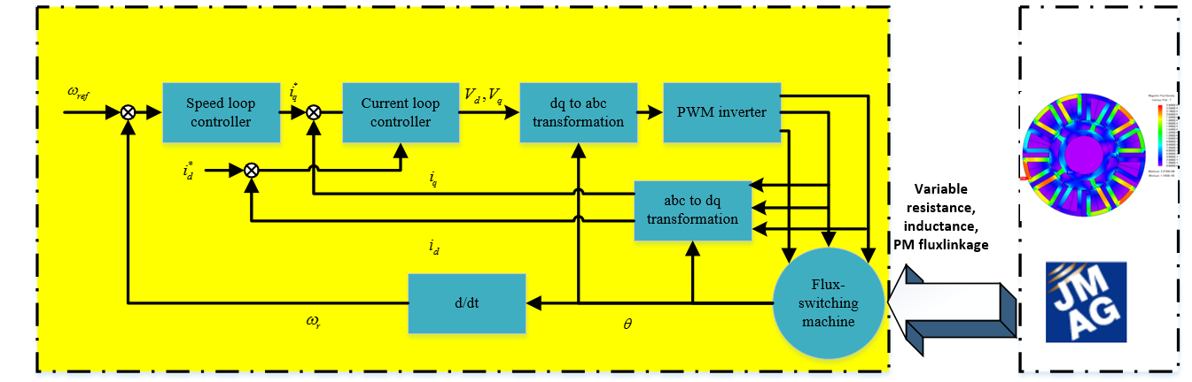
Fig.3 shows the block diagram for flux-switching machine in classical PI controller
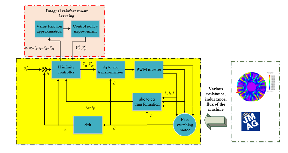
Fig.4 shows the block diagram for flux-switching machine in H infinity control with integral reinforcement learning
The H infinity control with integral reinforcement learning is a data driven characterisic whihc makes the system less sensitve to the unknown machine parameter uncertainties and external disturbance.